


Prepaid Water Mete With IC Card
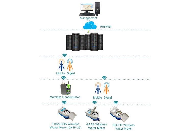
Difficulties in water charges have caused huge losses to water supply companies around the worldwhich has reduced water companies’ income and losses. IC card prepaid water meter is designedand manufactured to solve this problem.IC card prepaid water meter system is a system for collecting user water charges. lt controls the watersupply by water meter with a built-in valve.
All meters will be guaranteed against defects in workmanship and materials for a period of one (1) year from the date of acceptance.Defective meters or parts discovered within this period shall be replaced without charge upon return to the HBM Meters.
Application
IC card prepaid water meter is normally used in centralized water charging such as apartments, office buildings,school,Private water supply project etc.
Work process
1.Managers set user account information in software
2.Users recharge IC cards at the water charge office.
3. Users use IC cards read by water meters to recharge and pay fees for water meters.
4. When the balance is 0, the water meter automatically closes the valve and cuts off the water.
5. After recharging, users use their C cards read by water meter again, valve will open and restorethe water supply.
Software advantages
1.Managers set user account information in software.
2. Users recharge lC cards at the water charge office.
3. Users use IC cards read by water meters to recharge and pay fees for water meters.
4. When the balance is 0, the water meter automatically closes the valve and cuts off the water.
5. After recharging, users use their lC cards read by water meter again, valve will open and restorethe water supply.
MAIN TECHNICAL DATA
| Meter size Dia DN (mm) | Class | Q4 | Q3 | Q2 | Q1 |
| m3/h | L/h | ||||
| DN15 | 2 | 3.125 | 2.5 | 50 | 31.25 |
| DN20 | 5 | 4 | 80 | 50 | |
| DN25 | 7.875 | 6.3 | 126 | 79 | |
INDICATING ERROR
At low zone is ±5% from minimum flow rate (q1) to transitional flow rate (q2) exclusive boundary
At high zone is ±2% from transitional flow rate (q2) to overload flow rate(q4)
Working condition
1. Water temperature: ≤30°C(cold); ≤90°C(hot)
2. Pressure: ≤1.0Mpa
3. Maximum pressure loss: 0.063Mpa
4. Work environment: Class B
5. Working voltage: 36V(MBUS interface) or 12V(RS485 interface)
6. Sensitivity level of upstream flow field: U10
7. Downstream flow field sensitivity level: D5
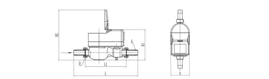
DIMENSIONS AND WEIGHT
| Size | Length L | Length L1 | Width B | Height H | Connecting Thread | Weight |
| mm | D | Kg | ||||
| DN15 | 258 | 165 | 85 | 115 | G3/4 | 1.5 |
| DN20 | 300 | 195 | 85 | 115 | G1 | 1.8 |
| DN25 | 330 | 225 | 85 | 115 | G1 1/4 | 2.2 |
Outline Dimension Drawing